Overview of Surface Finishing for Motor Commutators
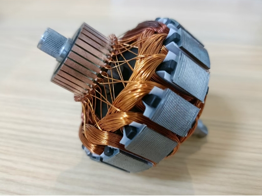
The commutator itself is an open ring, typically made of copper, with each segment connected to both ends of an armature coil. If the armature has multiple coils, the commutator similarly has multiple segments—one for each end of each coil. Spring brushes are positioned on each side of the commutator and make contact with it as it rotates, supplying voltage to the commutator segments and their corresponding armature coils. As the brushes pass through the gaps in the commutator, the supplied charge switches the commutator segments, thereby reversing the polarity of the armature coils. This switching of polarity within the coils maintains the armature's rotation in one direction.
The voltage amplitude between the brushes fluctuates between zero and maximum values, but always maintains the same polarity. The commutator is constructed in segments, each insulated from the others. When the brush transitions from one segment to another, there is an instantaneous moment where the brush contacts both segments simultaneously. This is called the neutral plane, where the induced voltage is zero. Otherwise, the brushes would short-circuit both ends of the coil, causing sparks due to high voltage.

Commutator Surface Requirements
For carbon brushes to run both quickly and smoothly on the commutator surface, the surface must possess a certain peak-to-valley height. To avoid excessive friction coefficients, a peak-to-valley height of 6-10 μm measured axially along the commutator surface is optimal. Under this height condition, a higher number of lathe grooves is preferable.
Simultaneously, the commutator's axis must run smoothly throughout the entire length of the copper segment. If the commutator surface is too smooth, the friction coefficient increases as the carbon brush moves across it, potentially causing crawling and producing a squeaking sound. Under such conditions, a normal metallic oxide contact layer cannot form on the commutator surface. Electrical sparks will result in uneven coloring of the commutator surface, thereby accelerating carbon brush wear. A favorable scenario is when the commutator surface occasionally roughens due to spark discharge. After a period, the carbon brushes eventually achieve smooth operation. However, in most cases, this unstable operation deforms the commutator into an oval shape, causing rapid carbon brush wear and shortening the motor's lifespan.
Characteristics of Fine Turning for Commutators The precision turning quality of the commutator's working surface has become critical to the commutation performance of brushed motors. Key quality requirements for fine turning of micro-motor commutator surfaces include: - Commutator outer diameter and length dimensions must meet process specifications - Outer circle runout relative to bearing stop must not exceed 0.006mm - Outer circle roundness must not exceed 0.003mm the height difference between segments must not exceed 0.0015mm, surface roughness must be Ra 0.1μm to Ra 0.8μm and Rz 0.8μm to Rz 3.2μm, the bottom of the engraved groove must be free of flash or stretching, surface patterns must be clear, smooth, and uniformly fine, and no copper filings should adhere to the surface.
Overview of Surface Finishing for Motor Commutators
The commutator itself is an open ring, typically made of copper, with each segment connected to both ends of an armature coil. If the armature possesses multiple coils, the commutator similarly features multiple segments—one for each end of each coil. Spring brushes are positioned on each side of the commutator and make contact with it as it rotates, supplying voltage to the commutator segments and corresponding armature coils. As the brushes traverse the gaps in the commutator, the supplied charge switches the
Commutator Surface Processing Characteristics
In the motor industry, commutator segments primarily use two materials: oxygen-free copper (or electrolytic copper) and silver-copper alloys. Both are predominantly copper-based. As copper is a typical ductile material, it exhibits a soft texture with low strength and hardness. It exhibits a high coefficient of linear expansion, generates significant heat during machining, and poses challenges in maintaining dimensional accuracy, often leading to copper shavings adhering to the surface. Additionally, the working surface of the commutator requires machining of recessed insulation slots. Precision turning involves intermittent cutting, which can cause burrs or stretching at the slot edges. During cutting, as the tool tip progressively penetrates the workpiece, plastic deformation occurs when cutting stress reaches and exceeds the material's yield strength. This results in shear slip deformation. Subsequently, as the shear plane compresses the material, filamentary or ribbon-like chips form and flow along the rake face.
The machined surface undergoes deformation and springback due to compression and friction from the rounded portion of the cutting edge and the rake face, resulting in fibering and work hardening. During commutator precision turning, appropriate tool materials, tool geometry parameters, and cutting parameters must be selected to control cutting temperature rise, deformation, and springback of the machined surface, thereby ensuring the quality of the commutator surface precision turning.
Commutator Precision Turning Tool Selection
Characteristics of PCD Tool Material Polycrystalline diamond (PCD) exhibits key advantages: high hardness; excellent wear resistance; low friction coefficient; high thermal conductivity; low thermal expansion coefficient; minimal affinity with non-ferrous metals and non-metallic materials. Its significant brittleness is a drawback, mitigated by optimizing tool angles and implementing appropriate machining processes to reduce impact effects. PCD materials are typically selected as pale yellow dodecahedrons. Those with crystalline purity and particle weights not exceeding 1.5 carats are considered excellent. Prior to grinding, PCD materials should undergo precision turning to orient the crystals, determine the crystal axis, and establish the grinding direction. Crystals should remain as intact as possible, with no cracks or inclusions at the crystal apex.
Tool Geometry Selection During turning operations, a minute portion of the workpiece remains unmachined on the finished surface. When feed rate f remains constant, increasing tool radius r reduces H and lowers surface roughness. However, excessively increasing r may cause mismatch with the finishing depth (i.e., cutting allowance) and feed rate, leading to squeezing of the machined surface during cutting. This results in chaotic tool marks, inconsistent surface roughness, discontinuities, and a rough finish. Based on the finishing allowance and surface roughness requirements for precision turning of micro-motor commutators, selecting a tool tip radius of R0.1mm is appropriate.
Tool Geometric Angle Selection
Considering the material properties of the commutator and the minimal allowances in precision turning for micro-motor commutators, a small rake angle y=12° is selected to ensure cutting edge sharpness. A large clearance angle α=14° is chosen to reduce friction between the tool's clearance face and the commutator surface, thereby controlling temperature rise and minimizing built-up edge formation. PCD turning tools feature exceptionally sharp edges, with low surface roughness and a small coefficient of friction, facilitating chip evacuation. However, due to the discontinuous copper busbar surface of the commutator and the presence of narrow grooves etched into mica, the cut copper chips form needle-like or granular shapes. If not promptly removed, these chips readily splatter or adhere to the commutator surface or tool tip, compromising surface quality.
Due to PCD material's poor heat resistance, it carbonizes (forming CO₂) and completely loses hardness when cutting temperatures exceed 700°C to 800°C. Silver-copper exhibits significant plastic deformation and high friction coefficient, causing substantial friction between the cutting edge and tool face during machining. Consequently, increasing cutting speed or feed rate leads to a sharp rise in cutting heat, disrupting normal machining. This poses obstacles to further improving product quality. During PCD turning operations, employing high-vacuum chip extraction methods is recommended. High-speed airflow promptly removes chips while simultaneously cooling the commutator and tool surfaces.
Conclusion
PCD material offers advantages such as high hardness, wear resistance, low surface roughness, and minimal friction coefficient. Tools made from this material, combined with appropriate tool geometry angles and cutting parameters for finishing commutators, fully meet product quality requirements. This eliminates the drawbacks of traditional finishing followed by hook tool grooving, thereby effectively improving motor commutation.