The commutator is a critical component in DC motors and certain AC motors, playing a vital role in switching the direction of current flow during motor operation. This seemingly simple device actually shoulders the key task of ensuring continuous motor rotation. Within the motor's system, the commutator functions like a precise traffic controller, methodically guiding current along predetermined paths to generate continuous rotational motion.
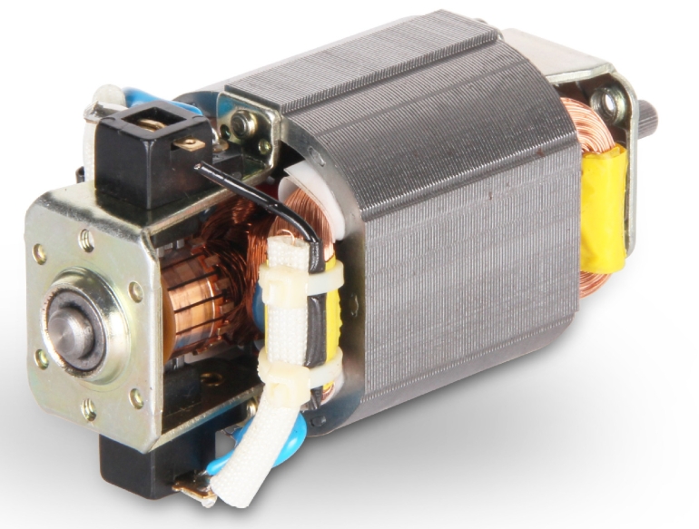
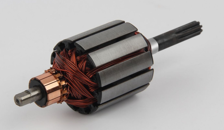
Physically, the commutator typically consists of multiple copper segments, insulated from each other and arranged in a cylindrical shape. These segments, known as commutator segments, connect to the motor's rotor windings. During operation, the commutator achieves periodic reversals of current direction within the rotor windings through sliding contact with brushes. This rhythmic switching of current direction forms the foundation for generating continuous rotational torque.
The commutator's operation is grounded in the fundamental laws of electromagnetic induction. When a conductor moves within a magnetic field and cuts through magnetic flux lines, an induced electromotive force (EMF) is generated within the conductor. Within the motor, this induced EMF is converted into sustained rotational power through the commutator's precise switching. Without this switching function provided by the commutator, a DC motor cannot achieve continuous rotational motion; it would only produce oscillating or intermittent rotation.
The commutator is a critical component in DC motors and certain AC motors, playing a vital role in switching the direction of current flow during motor operation. This seemingly simple device actually shoulders the key task of ensuring continuous motor rotation. Within the motor's system, the commutator functions like a precise traffic controller, methodically guiding current along predetermined paths to generate continuous rotational motion.
Physically, the commutator typically consists of multiple copper segments, insulated from each other and arranged in a cylindrical shape. These segments, known as commutator segments, connect to the motor's rotor windings. During operation, the commutator achieves periodic reversals of current direction within the rotor windings through sliding contact with brushes. This rhythmic switching of current direction forms the foundation for generating continuous rotational torque.
The commutator's operation is grounded in the fundamental laws of electromagnetic induction. When a conductor moves within a magnetic field and cuts through magnetic flux lines, an induced electromotive force (EMF) is generated within the conductor. Within the motor, this induced EMF is converted into sustained rotational power through the commutator's precise switching. Without this switching function provided by the commutator, a DC motor cannot achieve continuous rotational motion; it would only produce oscillating or intermittent rotation.
The Main Structure and Components of a Commutator
A complete motor commutator consists of multiple precision components working in concert. Commutator segments serve as the core elements, typically crafted from high-purity electrolytic copper due to its superior conductivity and wear resistance. These copper segments are machined into specific shapes and then assembled with precision to form a cylindrical structure. Each commutator segment is separated by mica or other high-performance insulating materials, ensuring electrical isolation while withstanding mechanical stresses generated by high-speed rotation.
The commutator's support structure is equally critical. A base, typically made from high-strength phenolic resin or specialized engineering plastics, provides mechanical support and insulation for the entire commutator. This base must withstand high temperatures, centrifugal forces generated by high-speed rotation, and the continuous friction from brushes. In modern high-performance motors, the commutator base may utilize metal materials, but its surface undergoes specialized insulation treatment to meet electrical performance requirements.
The brushes are the critical components in direct contact with the commutator, typically made of graphite or graphite-metal composite materials. Spring mechanisms maintain appropriate contact pressure between the brushes and the rotating commutator surface, ensuring reliable current conduction. The selection of brush materials and pressure regulation significantly impact the commutator's operational performance and service life, requiring careful design and selection based on specific application conditions.
Working Principle of Motor Commutators
The working principle of motor commutators is based on the perfect integration of electromagnetism and mechanical motion. When direct current is supplied through brushes to the rotating commutator, the current flows through the commutator segments into the rotor windings. As the rotor rotates, different commutator segments sequentially contact the stationary brushes, causing the current direction within the rotor windings to periodically reverse. This rhythmic switching of current direction ensures the rotor consistently experiences torque in the same direction within the magnetic field, enabling continuous rotation.
During motor operation, the commutator effectively functions as a mechanical switch. When the rotor reaches specific positions, the commutator automatically reconfigures the connection between the windings and the power source, enabling timely reversal of the current direction within the windings. This process must be precisely synchronized with the rotor's mechanical position; any timing deviation will degrade motor performance or even cause malfunction. This precise synchronization is a critical consideration in motor design.
The physical phenomena during commutation are quite complex. Ideally, current switching should occur instantaneously. However, in practice, the presence of winding inductance and contact resistance generates sparks and electromagnetic interference during commutation. Effective commutator design employs various techniques to minimize these undesirable effects, such as setting an appropriate commutation advance angle, using segmented commutator segments, or adding auxiliary poles. These measures significantly improve commutation quality, enhancing motor efficiency and extending its service life.
Application of Commutators in DC Motors
In DC motors, the commutator serves as an indispensable core component. Brush-type DC motors rely on the coordinated operation of the commutator and brushes to convert external DC power into alternating current within the rotor windings. This current conversion enables the rotor to maintain continuous rotation within the stator magnetic field. The excellent speed regulation characteristics and high starting torque of DC motors are largely attributable to the precise functioning of the commutator.
In series-wound DC motors, the commutator must not only handle substantial operating currents but also accommodate speed fluctuations caused by load variations. Commutators in these motors typically feature specialized designs, such as increased commutator segment counts or optimized segment shapes, to ensure reliable commutation performance under diverse operating conditions. Series-wound motors are commonly employed in applications requiring high starting torque, such as power tools and traction systems.
The commutator design in shunt-wound DC motors prioritizes stability during high-speed operation. Since the magnetic field in shunt-wound motors is relatively independent, their rotational speed is less affected by load variations. Consequently, the commutator must maintain excellent dynamic balance and reliable contact at high speeds. These motors are frequently employed in applications demanding precise speed control, such as machine tool spindle drives and precision instruments.
Special Applications of Commutators in AC Motors
Although commutators are primarily associated with DC motors, they can also be found in certain specialized types of AC motors. The universal motor is a classic example of an AC commutator motor, capable of operating under both DC and AC power sources. The commutator design in such motors resembles that of DC motors, but must account for additional challenges posed by the periodic changes inherent in alternating current.
The commutation process in AC commutator motors is more complex than in DC motors. Since the power supply voltage and current inherently change direction, the commutator must ensure the correct phase relationship between the rotor current and the stator magnetic field under these dynamic conditions. Such motors typically employ specially designed distributed windings and compensating windings to improve commutation performance under AC operating conditions.
Another type of AC motor using a commutator is the repulsion motor, which generates starting torque through the commutator and specially connected windings. During startup, this motor exhibits series-wound characteristics. Once it reaches a certain rotational speed, a centrifugal mechanism shorts part of the commutator segments, transitioning it to an operating mode similar to an induction motor. This design combines the high starting torque of a series-wound motor with the simple structure of an induction motor.
Manufacturing Process and Material Selection for Commutators
The production of commutators is a precision manufacturing process demanding stringent material selection and machining accuracy. Commutator segments typically employ highly conductive copper alloys containing trace amounts of silver or cadmium. These minor alloying elements preserve copper's high conductivity while enhancing material hardness and wear resistance. After precision stamping or machining, the copper components undergo surface treatment to improve wear resistance and reduce contact resistance.
The selection of insulating materials is equally critical. Traditional commutators utilize natural mica as insulation between commutator segments due to its excellent high-temperature resistance and electrical insulation properties. Modern high-performance commutators increasingly employ synthetic mica or specialty plastic films, which offer superior mechanical strength and thermal stability. The thickness of the insulating material must be precisely controlled; excessive thickness affects the overall dimensions of the commutator, while insufficient thickness may lead to insulation failure.
The assembly process directly impacts the commutator's operational performance and service life. Precision molds ensure correct positioning of all commutator segments and insulating layers, followed by a high-temperature, high-pressure curing process that bonds the entire assembly into a robust unit. High-end commutators undergo dynamic balancing after assembly to ensure smooth operation during high-speed rotation. For specialized applications, commutator surfaces may undergo silver or gold plating to further reduce contact resistance and minimize sparking.
Common Issues and Maintenance Methods for Commutators
Commutators encounter various typical problems during prolonged use. Surface oxidation is a common occurrence, particularly in high-temperature, high-humidity environments or when motors remain idle for extended periods. Oxidation layers increase contact resistance, leading to degraded motor performance and overheating. Regular inspection and cleaning of the commutator surface effectively prevents oxidation issues. Specialized commutator cleaners can effectively remove oxidation layers without damaging the copper segments.
Commutator segment burning is another frequent failure, typically caused by overload operation or improper brush pressure. Localized burning creates surface irregularities that accelerate brush wear and spark generation. Minor burns can be repaired through precision turning, while severe damage requires replacing the entire commutator. Preventing burning hinges on ensuring proper brush-to-commutator contact to avoid excessive local current density.
Brush sparking is a common phenomenon during commutator operation, but excessive sparking accelerates wear on both the commutator and brushes. Sparking arises from multiple causes, including mechanical factors (such as commutator eccentricity or brush vibration), electrical factors (such as excessive commutation induced electromotive force), and chemical factors (such as damage to the commutator surface coating). Spark levels can be effectively controlled by adjusting brush position, selecting appropriate brush materials, and maintaining a clean commutator surface.