The winding of a brushed motor rotor is a core process that determines the motor’s performance, service life and production efficiency. The winding method and structural design directly influence the winding resistance, sparking, copper loss and energy efficiency. The following provides a detailed explanation covering the classification of winding structures, mainstream winding methods, areas for process optimisation and equipment characteristics:
Common winding structural designs
1. Traditional one-to-one structure: hooks correspond one-to-one with slots
In traditional brushed motor rotors, the number of commutator hooks, the number of slots in the core, and the number of coils are exactly equal. For example, a 20-slot core corresponds to 20 commutator hooks, and during winding, the wire must be hooked once after each coil is completed. The core issue with this structure is that when the commutator has a small outer diameter and a large number of hooks, the spacing between windings at the hook points becomes too narrow, making inter-turn short circuits likely; furthermore, spot welding is difficult when the wire gauge is thick, resulting in low production efficiency. To address this issue, the industry has proposed an optimisation scheme involving halving the number of commutator segments: By halving the number of commutator segments/hooks, the enamelled wire is electrically connected at the hook after every two coils have been wound. This not only increases the spacing between wires to eliminate the risk of short circuits, but also widens the hook width to improve spot-welding efficiency. Furthermore, reducing the number of hook engagements enhances winding efficiency, ultimately achieving a 2–4% increase in motor power or a reduction in copper losses. This optimisation scheme is now widely adopted in the Shuangfei winding process.
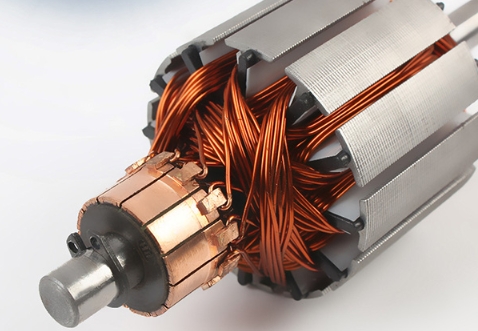
2. Neck-Winding Auxiliary Winding Structure
In traditional full-turn main winding designs, when motor performance and stator parameters are fixed, the resistance of the rotor windings tends to be too low. During repeated motor start-stops, excessive starting current leads to increased sparking at the carbon brush contacts, accelerating wear on the carbon brushes and commutator, which directly affects motor lifespan and poses potential hazards.
The neck-wound winding structure addresses this issue through the following improvements:
Following each main winding group, a secondary winding group is connected in series, comprising only 1%–10% of the number of turns of the main winding.
The secondary winding is not wound within the core slots, but is instead wound in an overlapping manner at the ‘rotor neck’ position between the end of the rotor core and the commutator.
All windings are wound sequentially from the first hook, through all main and auxiliary windings, and ending at the last hook. This does not alter the original winding pattern of the main windings; it merely increases the total resistance by adding a small number of windings, thereby suppressing the starting current and reducing wear.
Mainstream Winding Production Methods
In current industrial production, the winding of brush-type motor rotors primarily employs the double-fly-fork automatic winding process, with the following characteristics:
Advantages of Dual-Fork Winding
Compared to single-fork winding, dual-fork winding winds two sets of symmetrical coils simultaneously, offering higher winding efficiency and better natural dynamic balance of the rotor. Consequently, most factories adopt this process, which is suitable for the vast majority of brushed motor rotors with 8 slots or more. It is particularly well-suited for applications requiring high slot fill rates, such as automotive EPS motors and power tool motors.
Parameters and Features of Specialised Equipment
The core compatibility parameters for commercial dual-fork winding machines are as follows:
Suitable Core Outer Diameter:φ20–80 mm
Suitable Core Stack Thickness:20–100 mm
Compatible Enamelled Wire Diameter:φ0.1–1.1 mm
Fork Rated Speed:3000 rpm
This type of equipment utilises an AC servo control system, offering rapid start-up and high precision. It supports various winding methods, including single-slot single-hook, single-slot double-hook and double-layer winding, and can be integrated with upstream and downstream automated production lines, making it suitable for mass production.
Common Issues and Optimisation in the Winding Process
1. Optimisation of Insulation Short-Circuit Risks
Traditional rotors require the installation of multiple washers between the commutator and the armature, which are coated with an insulating layer. Insulation gaps are prone to wire snagging during winding, increasing the risk of short circuits between the commutator and the armature. The current industry-standard optimisation solution involves the use of an integrated paper rotor sleeve. This is rapidly secured to the shaft via its own mounting mechanism, creating a sealed, isolated space that effectively reduces the probability of wire snagging and minimises the risk of short circuits.
2. Rationale for Selecting Multi-Strand Parallel Winding
When a winding with a large cross-sectional area is required, multi-strand parallel winding using fine enamelled wire is typically preferred over a single thick strand. The key reasons are as follows:
Processing: Winding a single thick strand (wire diameter > 1.0 mm) is technically challenging; bending it can easily damage the enamel coating, causing wire damage. Multi-strand parallel winding can be completed using standard equipment, eliminating the need for customised machinery and thereby reducing production costs.
Performance: Multi-strand winding mitigates the skin effect, resulting in a higher current-carrying capacity than a single thick wire for the same cross-sectional area.
Maintenance: Thin enamelled wire is more widely stocked, making it easier to replace during repairs and facilitating after-sales service.