Precision Turning Process for Motor Commutator Surfaces
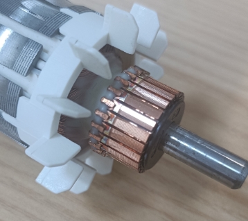
The commutator itself is typically an open ring made of copper, with each segment of the ring connected to both ends of an armature coil. If the armature contains multiple coils, the commutator will correspondingly have multiple segments—one for each end of each coil. Spring-loaded brushes are positioned on each side of the commutator and maintain contact with it as it rotates, supplying voltage to the commutator bars and the corresponding armature coils. As the brushes pass over the gaps in the commutator, the supplied electrical charge switches commutator bars, thereby reversing the polarity of the armature coils. This polarity switching in the coils keeps the armature rotating in one direction.
The voltage magnitude between the brushes fluctuates between zero and a maximum value but always maintains the same polarity. The commutator is constructed in segments insulated from one another. When a brush transitions from one segment to another, there is an instant where the brush contacts both segments simultaneously. This is known as the neutral plane, at which point the induced voltage is zero. Otherwise, the brush would short-circuit both ends of the coil and cause sparking due to high voltage.
Surface Requirements for Commutators
For carbon brushes to operate both rapidly and smoothly on the commutator surface, the surface must have a specific peak-to-valley height. To avoid an excessively high coefficient of friction, the optimal peak-to-valley height measured axially on the commutator surface is 6–10 μm. Under this height condition, a higher number of lathe tool marks is preferable.
Meanwhile, the axis of the commutator must run smoothly over the entire length of the copper segments. If the commutator surface is too smooth, the coefficient of friction between the carbon brush and the surface will increase, potentially causing crawling and chattering noises. In such cases, a normal metallic oxide film contact layer cannot form on the commutator surface. Electrical sparking will cause uneven discoloration of the surface, accelerating carbon brush wear.
In some instances, spark discharge may roughen the commutator surface, and after a period of operation, the carbon brush may eventually run smoothly. However, in most cases, unstable operation will render the commutator out-of-round, leading to rapid carbon brush wear and a shortened motor service life.
Characteristics of Commutator Precision Turning
The quality of precision turning on the commutator working surface has become critical to the commutation performance of brushed motors. Key quality requirements for precision turning of small and special motor commutators include:
Outer diameter and length dimensions conform to process specifications;
Runout of the outer circle relative to bearing seats ≤ 0.006 mm;
Circularity of the outer circle ≤ 0.003 mm;
Height difference between segments ≤ 0.0015 mm;
Surface roughness: Ra 0.1–0.8 μm, Rz 0.8–3.2 μm;
No burrs or stretching at undercut groove edges;
Clear, smooth, and uniformly textured surface patterns;
No adhesion of copper chips on the surface.
Machining Properties of Commutator Surfaces
In the motor industry, commutator bar materials mainly fall into two categories: oxygen-free copper (or electrolytic copper) and silver-copper alloys, both primarily composed of copper. Copper is a typical ductile material—tough, soft, low in strength and hardness, with a high coefficient of linear expansion. It tends to generate heat during machining, making dimensional accuracy difficult to control and prone to copper chip adhesion.
Additionally, the commutator working surface features undercut insulation grooves, making precision turning an intermittent cutting process that easily causes burrs or stretching at groove edges. During cutting, as the tool tip continuously penetrates the workpiece, plastic deformation and shear slip occur once shear stress reaches and exceeds the material’s yield strength. Under further compression from the tool rake face, filamentary or ribbon-shaped chips form and flow out along the rake face.
The machined surface undergoes extrusion and friction from the blunt edge of the cutting tool and the flank face, resulting in deformation, springback, fiberization, and work hardening. During commutator precision turning, appropriate tool materials, geometric parameters, and cutting parameters must be selected to control cutting temperature rise, as well as deformation and springback of the machined surface, ensuring high-quality precision turning.
Selection of Commutator Precision Turning Tools
Characteristics of PCD Tool Materials
Polycrystalline diamond composite materials (PCD) offer the following main advantages:
High hardness;
Excellent wear resistance;
Low friction coefficient;
High thermal conductivity;
Low thermal expansion coefficient;
Low affinity with non-ferrous and non-metallic materials.
The main disadvantage of PCD is its high brittleness, which can be mitigated by reasonably selecting tool angles and formulating matching machining processes to reduce impact loads.
Optimal PCD materials are typically pale yellow dodecahedral crystals with high purity and a particle weight ≤ 1.5 carats. Before grinding, PCD materials must be precisely oriented to determine crystal axes and grinding directions. Crystals should be as intact as possible, with no cracks or inclusions at the apex angles.
Selection of Tool Nose Geometry
During turning, a small portion of uncut material may remain on the machined surface. For a constant feed rate f, increasing the tool nose radius r reduces surface height H and improves roughness. However, excessive r, mismatched with the precision turning depth (cutting allowance) and feed rate, causes extrusion on the machined surface, leading to disordered tool marks, inconsistent thickness, breakpoints, and poor surface smoothness.
Based on the machining allowance and surface roughness requirements for small and special motor commutators, a tool nose radius of R0.1 mm is suitable for precision turning.
Selection of Tool Geometric Angles
Given the ductile properties of commutator materials and the small cutting allowance in precision turning, a small rake angle γ = 12° is chosen to maintain cutting edge sharpness, and a large clearance angle α = 14° to reduce friction between the tool flank and the commutator surface. This controls temperature rise and prevents built-up edge formation.
PCD turning tools have extremely sharp cutting edges, low edge roughness, and a low friction coefficient, facilitating chip evacuation. However, since the commutator consists of discontinuous copper bars with narrow undercut mica grooves, copper chips are needle-like or granular. If not removed promptly, they may splash or adhere to the commutator surface or tool tip, degrading surface quality.
PCD has poor heat resistance and will carbonize (forming CO₂) and lose hardness completely at cutting temperatures exceeding 700–800 °C. Silver-copper alloys exhibit high plastic deformation and friction, increasing friction against the cutting edge and tool face. Raising cutting speed or depth of cut drastically increases cutting heat, disrupting normal cutting and limiting quality improvement.
Therefore, a high-negative-pressure air extraction chip removal system is used during PCD turning. High-velocity airflow promptly removes chips while cooling both the commutator and tool surfaces.
Conclusion
PCD materials possess advantages including high hardness, wear resistance, low surface roughness, and a low friction coefficient. Using PCD tools with optimized geometric angles and cutting parameters for commutator precision turning fully meets product quality requirements. This method eliminates the drawbacks of traditional post-turning groove cleaning with hook tools and effectively improves motor commutation performance.